(THIS ADVICE MAY SAVE YOU MONEY AND MIGHT HELP INCREASE THE LIFE OF YOUR PRODUCT)

VUCAM XO – Portable Video Endoscope
Your Video Borescope has been designed to be used in an industrial environment. Its primary purpose is as an inspection device to allow you to obtain a view of areas that are difficult to inspect. When used as intended, it should work well and allow many inspections to be undertaken. However we receive a number of units back every year with damage caused by incorrect use – in many instances avoiding video endoscope damage could have been possible with a little thought.
DAMAGE – ARTICULATION FAILURE.
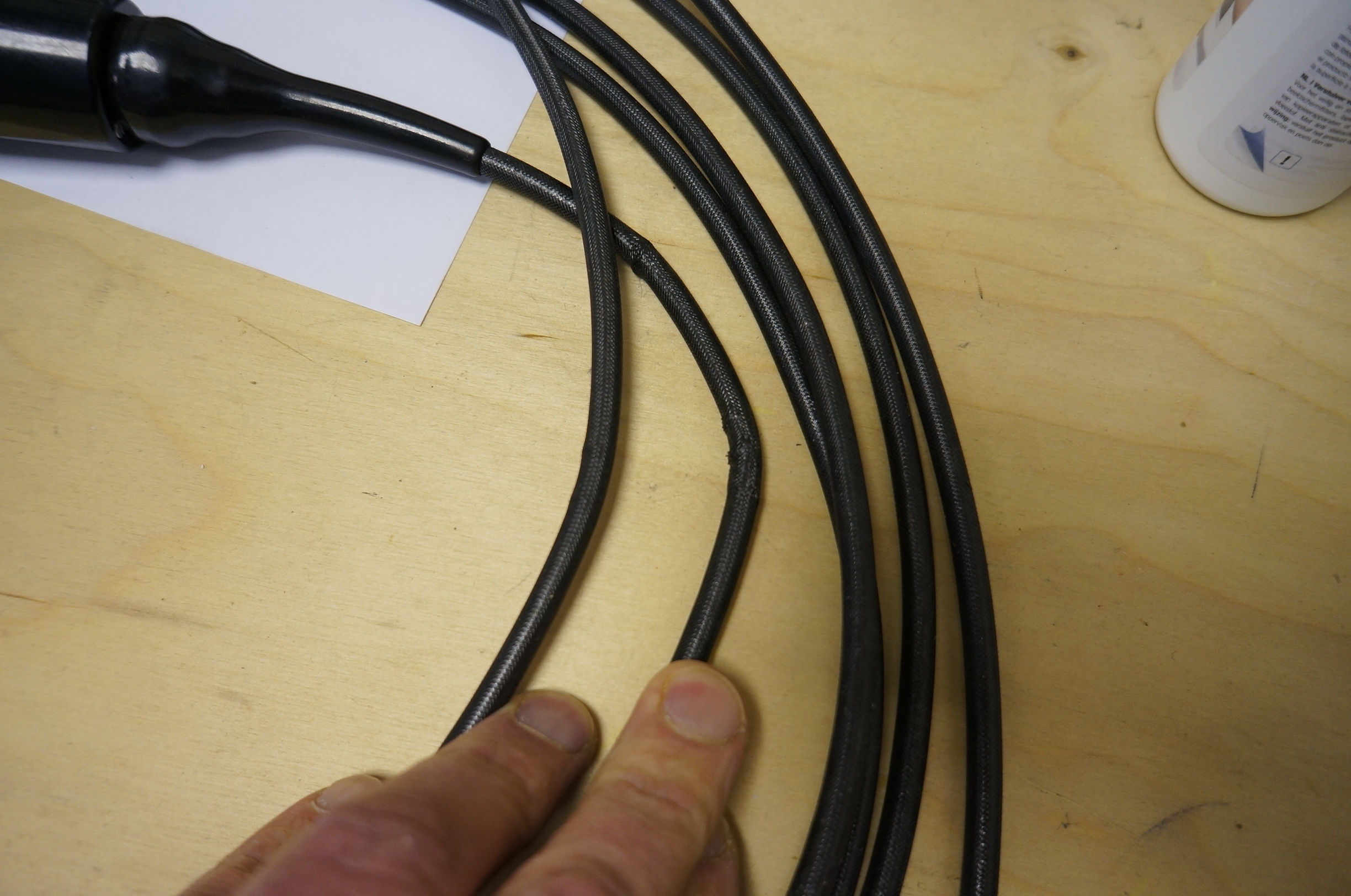
The tip of the unit is steered using 4 cables of approximately 0.5mm diameter, running within a sleeve – just like a brake cable on a bicycle – only much smaller. In the VUCAM system these are operated by turning the wheel in one or other direction, to cause the tip to bend. By combining the operation of the two wheels, you can articulate the tip such that it can inspect a wide range of area – and depending on the length of the borescope, the degree of articulation achievable will be between 130? to 100?, and in some cases even more. Longer lengths articulate less due to the length of the steering cables – they can and do stretch, particularly if you have deployed the unit around one or more bends. Once you have reached maximum articulation, there is no point in trying to get the tip to bend further – all you will succeed in doing is stretching the cable – sometimes to breaking point! If you exceed the elastic limit on the steering cable, but not break it, a permanent stretch will be imposed and you will find that the maximum degree of articulation will be reduced in that direction – the good news is that this is relatively easy for us to repair. If you snap a cable in one particular direction, then you will find that bending the tip in that direction is no longer possible, and that also returning the tip from being bent over in the opposite direction is very difficult if not impossible also. This will require a strip down of the bending neck, removal of the insertion tube and a replacement steering cable at the least.
TIP 1: Once the tip stops articulating (moving) in a particular direction, STOP TURNING THE WHEEL. If it’s not moving on the screen – its either stuck against a wall or reached maximum travel – either way, further turning of the wheels will only cause the cable to stretch. Also DON’T operate the system if its still in its box all coiled up – its fine to turn it on and check battery etc, but if you operate the articulation you run the risk of damaging the unit as its all coiled up and the friction may prevent the tip for moving……..
Sometimes it is important to hold the tip in place to study a region of interest – this is possible by using the friction brake on the wheels (or a probe lock function) – they act directly on the wheel and if you are looking for very fine adjustment it can also be helpful to use the brake to control the adjustment. Once you have finished using the brake/probe lock, it is VERY IMPORTANT to remember to remove the function – if the brake is holding the tip over in one direction, then if you start to move it may catch against an edge and potentially cause the cable to stretch or snap.
TIP 2: Always remove the probe lock / brake on completion of an inspection and ideally turn the wheels back to their neutral (Centre) setting – this should leave the tip in a flexible setting to allow the system to be moved / withdrawn easily and with minimal risk
Cable steered units are affected by friction, and operate best when perfectly straight. The real world doesn’t do straight very often, and frequently the inspection area is around one or more bends. Depending on how tight the bends are, and how many there are will determine how much articulation you might achieve – getting an inspection through 4 bends of 30? is much more likely than trying to inspect through 4 bends of 90? – and while you might reach the inspection point, articulation will be significantly reduced or not possible – you will find that achieving the articulation may be difficult and I would recommend following TIP 1 above.
AVOIDING VIDEO ENDOSCOPE DAMAGE – CAMERA HEAD
The head is normally mounted directly on the end of the bending neck. Depending on the manufacturer, the head may have a protection ring mounted, or one of many tip adapters, used to change the field of view and depth of field, and in some cases the direction of view (from straight ahead to sideways). NEVER operate the camera without either the tip protection ring or a tip adapter fitted – these add some protection to the optics and are usually held on by very fine threads – quite often a double thread to prevent accidental loss. Do NOT over tighten as the threads are fine and easily damaged – if the threads are damaged on the tip adapter this is a less costly repair than if the threads on the head are damaged.
TIP 3: Always check that the tip protector or a tip adapter is fitted before deployment, and that this is finger tight.
The optical path in a Video Borescope is the critical component. Always make sure this is clean – where possible blow off any dirt using a can of clean compressed air – if necessary use a local air line, but make sure the air pressure is gentle. If the lens is dirty, then it can be cleaned VERY GENTLY with an isopropyl alcohol mixture, ensuring you do every wipe with a clean, lint free cloth. Best practice would recommend that you do not use the same area of the cloth for successive wipes.
Do not drop the head onto a hard surface or the floor – while the design of the system is robust, the optical components lenses and also very carefully aligned – it is possible to crack or smash the lenses or damage the imaging chip. In this case, due to the manufacturing methods and small scale of the camera head, it is most likely you will need a new camera head.
AVOIDING VIDEO ENDOSCOPE DAMAGE
– INSERTION TUBE
Damaged insertion tube
The insertion tube is robust. Typically manufactured from a number of layers of different materials, it is designed to provide some stiffness to aid insertion while retaining sufficient flexibility to allow navigation around bends, and to protect the steering and electrical cables from damage – there is however a minimum bend radius so don’t over tighten a loop or it will buckle locally and this may affect the articulation. Similarly a commonly seen damage is a flattened insertion tube region where it has been stepped on or an item of equipment accidentally placed on it. If the rest of the camera system is working fine and there is an area of damage affecting the articulation, we may be able to open this up again sufficiently to recover the articulation, however this is not always the case, and that point will forever remain weakened.
TIP 4: Ensure you have sufficient space cleared of obstruction around your working area. When using longer insertion tube lengths, try to tape off your working area to prevent accidental damage by others.
The outer layer of most insertion tubes is a layer designed to help reduce damage, and is typically manufactured from either a tungsten or stainless steel braid. The braids are tough, but are manufactured from fine wires and they wear and bend, may either wear through, or work harden and snap – either way you will end up with worn insertion tube. This process can be delayed by taking a few precautions when performing inspections – particularly when carrying out inspections through rough openings and tight bends. It may be helpful to prepare a guide tube to protect the insertion tube from rough edges – this can be as simple a you like – a length of suitable hose pipe can be as effective as a custom designed sleeve.
TIP 5: Use a guide tube to help protect he insertion tube from sharp edges
Longer inspections may prove difficult without a pushing aid – and if bends are involved then if the diameter of the insertion tube is much less than the diameter of the tube or pipe being inspected, then there is a risk of the insertion tube not moving forward, but building up coils behind the head – if these then lock up you may have difficulty extracting the insertion tube – this may be a particular problem if the inspection is vertically upward. If you pull hard backwards when the insertion tube has coiled you risk damaging the system and getting it irretrievably stuck. If you are using a pushing aid, it is best to fix it some distance behind the articulating head so that it allows unhindered articulation.
If access to the job is through an orifice greater than 50mm (2”) and the pipe, tube or region of interest is equally wide or even wider, then it is probably better to use a different camera system than an endoscope – larger camera heads can support larger imaging chips and more light delivery, giving greater image quality – and typically these systems are less expensive to both buy and maintain.
Sometimes it may be tempting to use the camera to clear an obstruction in a pipe or tube – you have just spent some time in getting to find the problem, you can see it on the screen, it’s a natural instinct to think that a couple of sharp jabs might just dislodge the blockage – DON’T! – you wouldn’t use your mobile phone to hammer in a nail (would you?) – so just because the video borescope looks tough and robust doesn’t mean it’s a battering ram as well as a camera system. Some systems are supplied with small tools that can be fixed onto the front, or have a working channel that allows the deployment of a small tool and that’s great, but please don’t use the camera head to do this.
There is a simple fact that over time and with regular use, a video borescope will wear and eventually need some repair – avoiding video endoscope damage in the longer term is difficult due to the nature of the inspection work. However by following some of the tips above and being aware of the failure mechanisms that are commonly seen, users can reduce the number of inadvertent failures, improve their experience of inspections and manage the overall cost of ownership.
To download a copy of this document click HERE (opens in another window).
If you have a particular inspection and would like some advice on a suitable camera then please don’t hesitate to contact us on +44 (0)1892 539503 or via email info@crimsoniv.co.uk.
